
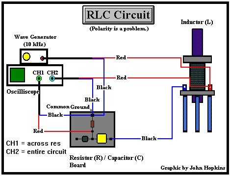
RLC Circuit
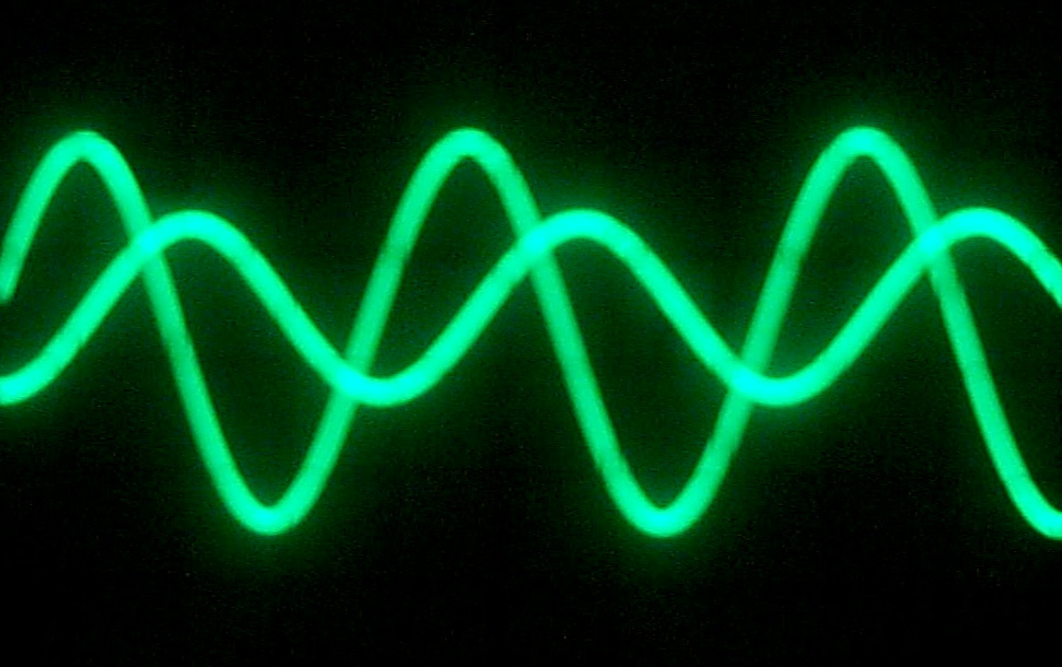
Channel 1:
Higher amplitude trace is across resistor.
Channel 2: Lower amplitude trace
is across the entire circuit (resistor, capacitor, and inductor)
![]()
![]() Circuit board with
Resistor ( 470 ohms), Capacitor (103k farads), and Inductor (~ 2.3 ohms)
Circuit board with
Resistor ( 470 ohms), Capacitor (103k farads), and Inductor (~ 2.3 ohms)
![]() Wave Generator set at 1k, dial at
2.2, on SIN WAVE
Wave Generator set at 1k, dial at
2.2, on SIN WAVE
![]() 2 Channel Oscilliscope
set at 5 volts
/ division and 50 ”
Sec
2 Channel Oscilliscope
set at 5 volts
/ division and 50 ”
Sec
![]()